Appendix C: CAN Communications Protocol
Hardware
The CAN hardware interface used is compatible with the CAN 2.0B standard. The supported bit rates (bits per second) are 1 Mbps, 500 kbps (default), 250 kbps, 125 kbps, 100 kbps and 50 kbps.
Software
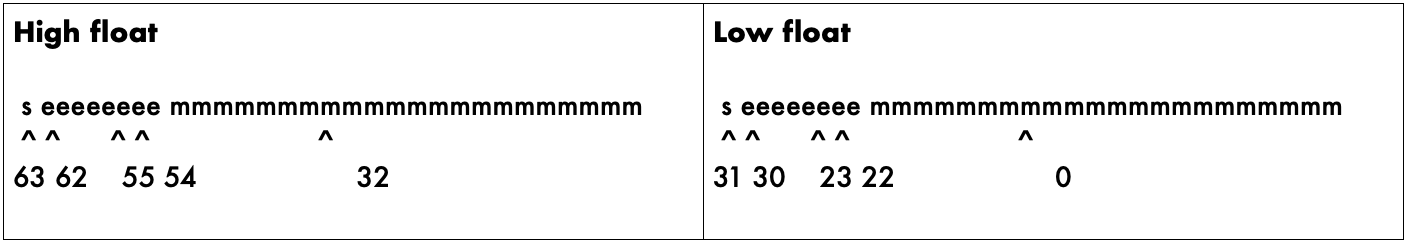
The CAN protocol uses data frames for most communication. Remote frames are also enabled. The identifier field uses the standard frame definition length of 11 bits, with identifiers 0x7F0 to 0x7FF reserved for use by the WaveSculptor bootloader. The bootloader will send a message with identifier 0x7F1 at 500kbit after a system reset. All measurement data is transmitted using IEEE single-precision 32-bit format (IEEE 754) with most significant byte (MSB) sent first.

Identifier
The identifier field has been split into two sections for Prohelion devices. Bits 10-5 contain the device identifier and bits 4-0 contains the message identifier associated with that device, as shown in Figure 2. This means that there is a maximum of 63 Prohelion device that can be on the CAN bus at any one time. The 64th location is reserved for the bootloader. Each Prohelion device can have 31 different types of messages. The first message identifier is used by the device identification message. Two device slots could be used if more messages per device were required, however this has not been required yet.
The term Base Address is used instead of Device Identifier in the Windows configuration program. Base Address is simply the Device Identifier multiplied by 32. Using this term makes it more obvious what range of CAN identifiers have been used. As an example, there may be a Prohelion driver controls at base address 0x400, a left wheel WaveSculptor motor controller at 0x420 and a right wheel WaveSculptor motor controller at 0x440. So, address range 0x400 – 0x45F would be used by this Prohelion system.

Data Field
The data field in all frames is fixed at 8 bytes (64 bits) which allows space for two IEEE 754 32-bit floating point variables as shown in Figure 3. The data field is sent and expected to be received least significant byte first. This allows a direct overlay of a float[2] array and char[8] array on a little endian processor, such as an Intel x86, the TI DSP in the WaveSculptor, or the MSP430 micro in the driver controls product.
Units
Please note that variables described in the following packets with units of percent “%” should be sent with a minimum floating-point value of 0.0 and a maximum value of 1.0. Do not send 100.0 as the maximum value.
Drive Commands
These are data frames broadcast from the driver controls to any listening motor controller. These commands contain desired set points for the control software to operate the controller. The commands are sent as required, however there is a maximum permissible delay between consecutive Motor Drive commands.
The identifier of a received command will contain the base address of the device from which the message was sent and a message identifier offset. The base address of the sending device is a preset value stored in internal memory, which can be set during initial configuration of the motor controller using the configuration utility.
Motor Drive Command
ID: Driver Controls Base Address + 0x01
Interval: 100ms
| Variable | Bits | Type | Description |
|---|---|---|---|
Motor Current |
63..32 | % | Desired motor current set point as a percentage of maximum current setting |
Motor Velocity |
31..0 | rpm | Desired motor velocity set point in rpm |
The WaveSculptor motor controller must receive a Motor Drive Command frame at least once every 250ms. If this does not occur, the controller will assume that communications have failed and will halt all motor control functions, placing the system into neutral and coasting until another valid command is received.
Motor Power Command
ID: Driver Controls Base Address + 0x02
Interval: 100ms
| Variable | Bits | Type | Description |
|---|---|---|---|
Bus Current |
63..32 | % | Desired set point of current drawn from the bus by the controller as a percentage of absolute bus current limit. |
Reserved |
31..0 | - | - |
Reset Command
ID: Driver Controls Base Address + 0x03
| Variable | Bits | Type | Description |
|---|---|---|---|
Unused |
63..32 | - | - |
Unused |
31..0 | - | - |
Send a command from this address to reset the software in the WaveSculptor, not used during normal operation but can be used to reset the device if necessary.
Drive Command Examples
Ignoring the added complexity of bus and thermal limiting, the WaveSculptor operates such that it will use the maximum available current (torque) to try and achieve the desired velocity. This is true for both accelerating and decelerating operation, i.e. the WaveSculptor will automatically regeneratively brake if a setpoint velocity is provided that is slower than the current speed.
Two main drive modes will be used in a normal vehicle setup: torque control; and velocity (cruise) control. A conventional vehicle runs in torque control mode, where the position of the accelerator (gas) pedal controls the amount of torque produced by the engine. In an electric system, the motor current is proportional to torque, and can be easily regulated, as can the velocity.
To run the motor in torque control mode, set the velocity to an unobtainable value such as 20000rpm. Set the current to a value that is proportional to your accelerator pedal position. If you wish to drive in reverse, set the velocity to -20000rpm. The motor will operate the same as a normal car, and will coast down to a stop if the driver removes their foot from the pedal.
To run the motor in velocity (cruise) control mode, set the current to your maximum desired acceleration force (usually 100%), and set the velocity to the desired speed. The WaveSculptor will use the setpoint current to keep the vehicle at the setpoint speed, and will use both drive and regenerative braking to do so. Use this mode to regeneratively brake to a halt by setting current to your desired braking force, and setting velocity to zero.
Motor Controller Broadcast Messages
Data frames containing telemetry values are periodically broadcast onto the bus by the WaveSculptor. Broadcast of these values can be individually enabled and disabled via the Windows configuration software.
Any of these telemetry values can be requested at any time (no matter if enabled or disabled) by sending the appropriate RTR packet on the CAN bus. For example, with a WaveSculptor22 configured at base address 0x400, your device should send an empty packet onto the CAN bus with an ID of 0x402 and the RTR bit set. The WaveSculptor22 will reply immediately with a packet from ID 0x402 containing the latest bus voltage and current readings.
Identification Information
ID: Motor Controller Base Address + 0x00
Interval: 1 Second
| Variable | Bits | Type | Description |
|---|---|---|---|
Serial Number |
63..32 | Uint32 | Device serial number, allocated at manufacture. |
Prohelion ID |
31..0 | Uint32 | Device identifier. 0x00004003 |
The periodic broadcast of this message cannot be disabled. It is needed to find the motor controller on the network if the base address is lost or mis-configured.
Status Information
ID: Motor Controller Base Address + 0x01
Interval: 200ms
| Variable | Bits | Units | Description |
|---|---|---|---|
Receive Error Count |
63..56 | Uint8 | The DSP CAN receive error counter (CAN 2.0) |
Transmit Error Count |
55..48 | Uint8 | The DSP CAN transmission error counter (CAN 2.0) |
Active Motor |
47..32 | Uint16 | The index of the active motor currently being used. |
Error Flags |
31..16 | Uint16 | Flags Indicate Error |
| Bits | Parameter | ||
| 15..9 8 7 6 5 4 3 2 1 0 |
Reserved Motor Over Speed (15% overshoot above max RPM) Desaturation Fault (IGBT desaturation, IGBT driver OVLO) 15V Rail under voltage lock out (UVLO) Config read error (some values may be reset to defaults) Watchdog caused last reset Bad motor position hall sequence DC Bus over voltage Software over current Hardware over current |
||
Limit Flags |
15..0 | Uint16 | Flags Indicate which control loop is limiting the output current of the motor controller |
| Bits | Parameter | ||
| 15..7 6 5 4 3 2 1 0 |
Reserved IPM Temperature or Motor Temperature Bus Voltage Lower Limit Bus Voltage Upper Limit Bus Current Velocity Motor Current Output Voltage PWM |
Bus Measurement
ID: Motor Controller Base Address + 0x02
Interval: 200ms
| Variable | Bits | Units | Description |
|---|---|---|---|
Bus Current |
63..32 | A | Current drawn from the DC bus by the controller. |
Bus Voltage |
31..0 | V | DC bus voltage at the controller. |
Velocity Measurement
ID: Motor Controller Base Address + 0x03
Interval: 200ms
| Variable | Bits | Units | Description |
|---|---|---|---|
Vehicle Velocity |
63..32 | m/s | Vehicle velocity in metres/second. |
Motor Velocity |
31..0 | rpm | Motor angular frequency in revolutions per minute. |
Phase Current Measurement
ID: Motor Controller Base Address + 0x04
Interval: 200ms
| Variable | Bits | Units | Description |
|---|---|---|---|
Phase C Current |
63..32 | Arms | RMS current in motor Phase C. |
Motor Velocity |
31..0 | Arms | RMS current in motor Phase B. |
While the motor is rotating at speed these two currents should be equal. At extremely low commutation speeds these two currents will only match in one third of the motor position, the other two thirds will involve current also flowing in Phase A.
Motor Voltage Vector Measurement
ID: Motor Controller Base Address + 0x05
Interval: 200ms
| Variable | Bits | Units | Description |
|---|---|---|---|
Vd |
63..32 | V | Real component of the applied non-rotating voltage vector to the motor. |
Vq |
31..0 | V | Imaginary component of the applied non-rotating voltage vector to the motor. |
Motor Current Vector Measurement
ID: Motor Controller Base Address + 0x06
Interval: 200ms
| Variable | Bits | Type | Description |
|---|---|---|---|
Id |
63..32 | A | Real component of the applied non-rotating current vector to the motor. This vector represents the field current of the motor. |
Iq |
31..0 | A | Imaginary component of the applied non-rotating current vector to the motor. This current produces torque in the motor and should be in phase with the back-EMF of the motor. |
Motor BackEMF Measurement/Prediction
ID: Motor Controller Base Address + 0x07
Interval: 200ms
| Variable | Bits | Type | Description |
|---|---|---|---|
BEMFd |
63..32 | V | By definition this value is always 0V. |
BEMFq |
31..0 | V | The peak of the phase to neutral motor voltage. |
15V Voltage Rail Measurement
ID: Motor Controller Base Address + 0x08
Interval: 1 second
| Variable | Bits | Type | Description |
|---|---|---|---|
15V supply |
63..32 | V | Actual voltage level of the 15V power rail. |
Reserved |
31..0 | - | - |
3.3V & 19.V Voltage Rail Measurement
ID: Motor Controller Base Address + 0x09
Interval: 1 second
| Variable | Bits | Type | Description |
|---|---|---|---|
3.3V supply |
63..32 | V | Actual voltage level of the 3.3V power rail. |
1.9V supply |
31..0 | V | Actual voltage level of the 1.9V DSP power rail. |
Reserved
ID: Motor Controller Base Address + 0x0A
Interval: -
| Variable | Bits | Type | Description |
|---|---|---|---|
Reserved |
63...32 | - | - |
Reserved |
31...0 | - | - |
Heat-sink & Motor Temperature Measurement
ID: Motor Controller Base Address + 0x0B
Interval: 1 second
| Variable | Bits | Type | Description |
|---|---|---|---|
Heat-sink Temp |
63..32 | °C | Internal temperature of Heat-sink (case) |
Motor Temp |
31..0 | °C | Internal temperature of the motor. |
DSP Board Temperature Measurement
ID: Motor Controller Base Address + 0x0C
Interval: 1 second
| Variable | Bits | Type | Description |
|---|---|---|---|
Reserved |
63..32 | - | - |
DSP Board Temp |
31..0 | °C | Temperature of the DSP board. |
Reserved
ID: Motor Controller Base Address + 0x0D
Interval: 1 second
| Variable | Bits | Type | Description |
|---|---|---|---|
Reserved |
63..32 | - | - |
Reserved |
31..0 | - | - |
Odometer & Bus AmpHours Measurement
ID: Motor Controller Base Address + 0x0E
Interval: 1 second
| Variable | Bits | Type | Description |
|---|---|---|---|
DC Bus AmpHours |
63...32 | Ah | Charge flow into the controller DC bus from the time of reset. |
Odometer |
31...0 | m | Distance the vehicle has travelled since reset. |
Slip Speed Measurement
ID: Motor Controller Base Address + 0x17
Interval: 200ms
| Variable | Bits | Type | Description |
|---|---|---|---|
Slip Speed |
63..32 | Hz | Slip speed when driving an induction motor. |
Reserved |
31..0 | °C | - |
Configuration Commands
Active Motor Change
ID: Motor Control Base Address + 0x12
| Variable | Bits | Units | Description |
|---|---|---|---|
Active Motor |
63..48 | WORD | Desired active motor (0 to 9) |
Configuration Access Key |
47..0 | ASCII | Must spell “ACTMOT” in ASCII (0x54 4F 4D 54 43 41) |
Send this command to change the active motor. Note that the controller will save the active motor to the EEPROM config memory, so what you send will survive a reset. This has a downside that you do not want to be sending it constantly, as you'll wear out the EEPROM.
Example to set the active motor to motor slot 5:
CAN ID = 0x412, Data = 0x00 05 54 4F 4D 54 43 41