Prohelion BMS D1000 Gen2 - Hardware Components
This section provides information on the Prohelion D1000 Gen2 Battery Management Unit (BMU).
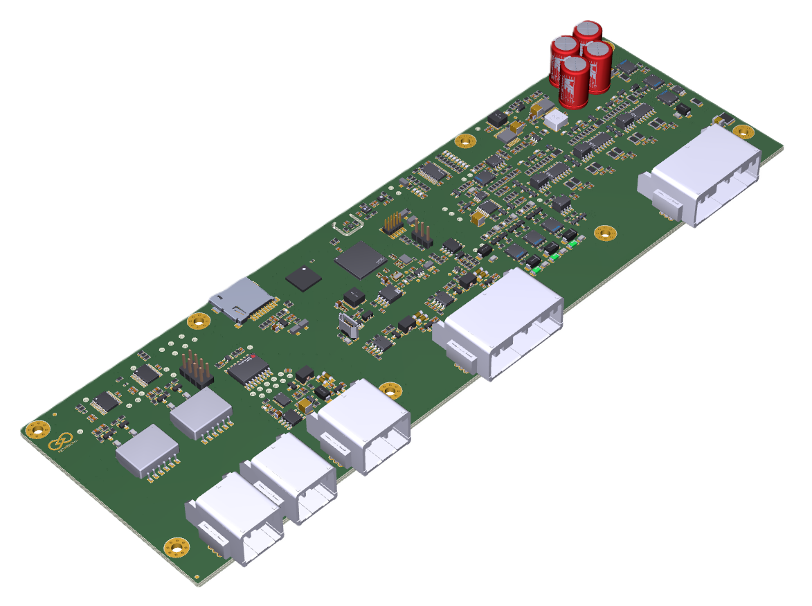
Figure 1: Prohelion BMS D1000 Gen2 BMU
Features
- 5 contactor outputs
- 3 low-side switches
- 2 non-isolated CAN bus networks (Internal and Reserved)
- 1 isolated CAN bus network (External)
- Pressure and humidity sensor
- VOC and NOx sensor
- Temperature sensors
Specifications
| Parameter |
Value |
| BMS Supply Voltage |
12 V / 24 V (two variants) |
| BMS Supply Current |
80 mA (excluding contactors) |
Dimensions
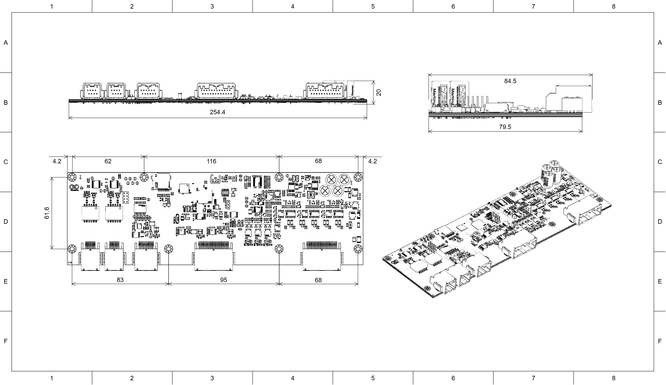
Figure 2: Prohelion BMS D1000 Gen2 BMU Drawing 1
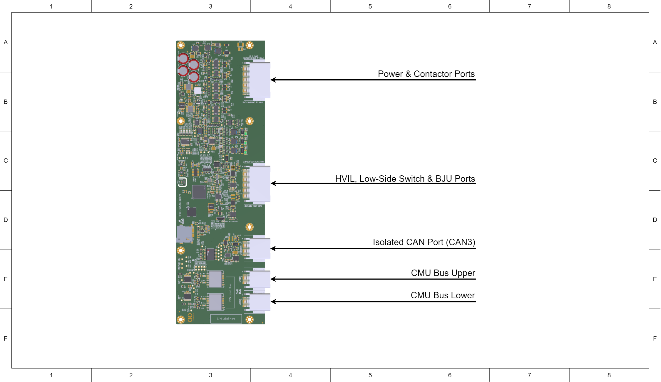
Figure 3: Prohelion BMS D1000 Gen2 BMU Drawing 2
Connectors and Pinouts
| Connector Name |
Receptacle Part Number |
Plug Part Number |
| Power & Contactor Ports |
JAE Electronics MX34R24HF4T |
JAE Electronics MX34024SF1 |
| HVIL, Low-Side Switch & BJU Ports |
JAE Electronics MX34R24HF4T |
JAE Electronics MX34024SF1 |
| Isolated CAN Port (CAN3) |
JAE Electronics MX34R12HF4T |
JAE Electronics MX34012SF1 |
| CMU Bus Upper |
JAE Electronics MX34R08HF4T |
JAE Electronics MX34008SF4 |
| CMU Bus Lower |
JAE Electronics MX34R08HF4T |
JAE Electronics MX34008SF4 |
| Pin Number |
Label |
Pin Number |
Label |
| 1 |
BMS Input Power+ (12V/24V) |
13 |
BMS Input Power+ (12V/24V) |
| 2 |
BMS Input Power- |
14 |
BMS Input Power- |
| 3 |
BMS Ground |
15 |
Contactor 1 Positive |
| 4 |
Contactor 1 Auxiliary Negative |
16 |
Contactor 1 Auxiliary Positive |
| 5 |
BMS Ground |
17 |
Contactor 2 Positive |
| 6 |
Contactor 2 Auxiliary Negative |
18 |
Contactor 2 Auxiliary Positive |
| 7 |
BMS Ground |
19 |
Contactor 3 Positive |
| 8 |
Contactor 3 Auxiliary Negative |
20 |
Contactor 3 Auxiliary Positive |
| 9 |
BMS Ground |
21 |
Contactor 4 Positive |
| 10 |
Contactor 4 Auxiliary Negative |
22 |
Contactor 4 Auxiliary Positive |
| 11 |
BMS Ground |
23 |
Contactor 5 Positive |
| 12 |
Contactor 5 Auxiliary Negative |
24 |
Contactor 5 Auxiliary Positive |
HVIL, Low-Side Switch & BJU Ports
| Pin Number |
Label |
Pin Number |
Label |
| 1 |
HVIL Positive |
13 |
HVIL Input |
| 2 |
BMS Ground |
14 |
CAN1 Shield |
| 3 |
CAN1 Low |
15 |
CAN1 High |
| 4 |
Not Connected |
16 |
BJU Power |
| 5 |
Low-Side Switch 3 Negative |
17 |
Low-Side Switch 3 Positive |
| 6 |
Not Connected |
18 |
Low-Side Switch 3 Sense |
| 7 |
Low-Side Switch 2 Negative |
19 |
Low-Side Switch 2 Positive |
| 8 |
Not Connected |
20 |
Low-Side Switch 2 Sense |
| 9 |
Low-Side Switch 1 Negative |
21 |
Low-Side Switch 1 Positive |
| 10 |
Not Connected |
22 |
Low-Side Switch 1 Sense |
| 11 |
BMS Ground |
23 |
CAN2 Shield |
| 12 |
CAN2 Low |
24 |
CAN2 High |
Isolated CAN Port (CAN3)
| Pin Number |
Label |
Pin Number |
Label |
| 1 |
CAN3 Low |
7 |
CAN3 High |
| 2 |
CAN3 Ground |
8 |
CAN3 Power |
| 3 |
Not Connected |
9 |
CAN3 Shield |
| 4 |
CAN3 Low |
10 |
CAN3 High |
| 5 |
CAN3 Ground |
11 |
CAN3 Power |
| 6 |
Not Connected |
12 |
CAN3 Shield |
CMU Bus Port Upper
| Pin Number |
Label |
Pin Number |
Label |
| 1 |
TX Positive |
5 |
TX Negative |
| 2 |
Not Connected |
6 |
Not Connected |
| 3 |
Not Connected |
7 |
Not Connected |
| 4 |
RX Negative |
8 |
RX Negative |
CMU Bus Port Lower
| Pin Number |
Label |
Pin Number |
Label |
| 1 |
TX Positive |
5 |
TX Negative |
| 2 |
Not Connected |
6 |
Not Connected |
| 3 |
Not Connected |
7 |
Not Connected |
| 4 |
RX Negative |
8 |
RX Negative |