Configuration Tools
The wsConfig program has three configuration tools that are very important to setting up the WaveSculptor motor controller to drive your motor. These tools are PhasorSense, ParamExtract and ImExtract.
The next three section describe how to use these three tools.
PhasorSense
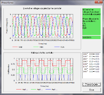
PhasorSense is designed to find phase and hall sequence, along with the relation between them. Plots of both the three phase voltages and the motor hall effect position logic are displayed. This should assist finding any errors with motor/controller set up.
To start a PhasorSense Acquisition press the Phase Acquire button in the bottom right corner of the window. You then have 10 seconds to spin the motor with an electrical motor frequency of more than 12Hz. Even on a fairly low pole count motor of 4 pole pairs this is only 180RPM, which is achievable by hand. The high-voltage DC bus does not have to be connected for this test. The WaveSculptor uses hall edges to decide if the speed is sufficient, so if the halls are not connected to the controller a "Failed to obtain sufficient speed" message will be given.
If the acquisition is successful, results similar to the ones shown in Figure 6 should be displayed and you will be presented with a message box asking if you want to save the PhasorSense results. If you a happy with the results of the acquisition save the results to your chosen motor slot, otherwise cancel the save, fix the test rig and try again.
NOTE: When an Encoder or Resolver motor interface board is connected the hall input should appear as a single “saw-tooth” pattern ranging from 0 to 1 inclusive (If full 0 to 1 range isn't being seen, then verify that the Encoder count in the active motor configuration is correct).
Paramextract
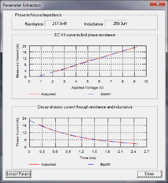
ParamExtract is designed to find the motor stator resistance and inductance.
This acquisition process requires the bus voltage and motor to be connected to the WaveSculptor. For best results the bus voltage should be no larger than needed to overcome the line resistance (a 60V bus voltage is usually plenty). The higher the PWM required to source 20A out of phase CB of the WaveSculptor the more accurate the calculation of line resistance and inductance.
The motor may rotate briefly during this test, as such KEEP AWAY FROM THE MOTOR while running this test. It should also be disconnected from the drive wheel of the car, or the wheel should be raised up from the ground before performing this test.
The ExtractParams button starts the acquisition process.
The algorithm linearly ramps the current in phase CB from 0A to 20A then switches off, noting the slope of the ramp and time constant of the decay. This process should take no more than a few seconds, after which the results will be presented on screen as shown in Figure 7.
A message box will appear asking if you wish to save the results.
NOTE: If the motor moved during the test, do not save the results. Repeatedly run the test until there is no noticeable movement during the test. This is because motor movement creates a voltage, which influences the reading. If the acquisition was good, the blue dashed best-fit curve should lie neatly on top of the acquired curve. Once a good fit is achieved without motor movement, allow the software to save the results to the motor slot you are configuring.
Imextract
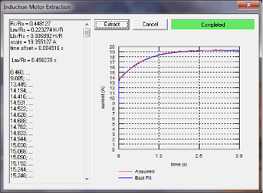
ImExtract is designed to find the rotor resistance and inductance in induction motors.
This acquisition process requires the bus voltage and motor to be connected to the WaveSculptor (a 60V bus voltage is usually plenty).
An induction motor should not move during this test, however, it is still recommended to KEEP AWAY FROM THE MOTOR while running this test.
The Extract button starts the acquisition process, which can last for 30 seconds. The results will be presented on the screen as shown in Figure 8. The blue best-fit curve should lie neatly on top of the acquired red curve. If the two curves are well matched, save the acquired rotor constants to the configuration file. If the test failed or the two curves are poorly matched, check the test rig and try again.


