CAN Bus
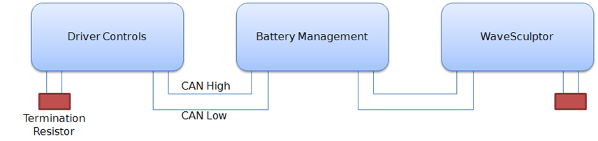
The CAN bus is structured as a linear network, with short stubs branching from 'T' connectors on the main bus backbone to each device. The CAN bus data lines must be terminated at each end of the main bus with 120 ohm resistors between the CAN-H and CAN-L signals.
In the range of Prohelion EV products, including the WaveSculptor 200, EV Driver Controls, and BMS Pack Master, the CAN connections are implemented with an 'in' and an 'out' connector, therefore placing the 'T' on the device, resulting in a very short fixed-length stub on the circuit board of each device. This is ideal from a signal integrity and network performance point of view.
The WaveSculptor motor controller uses the CAN bus to receive commands and transmit telemetry, as well as to provide low-voltage DC power to operate the controller electronics.
Therefore, a basic system consists of three major components:
- WaveSculptor motor controller
- Driver controls interface to pedals, switches & gauges
- Power supply (nominally 12V DC) to operate the system
Other components can also be added to the network. Items typically found in an electric vehicle would include: 4. LCD and other driver information displays 5. Battery management system 6. Multiple motor controllers 7. Datalogging
CAN Wiring
The CAN data lines (CAN-H and CAN-L) must be implemented with twisted-pair wire for proper data integrity. The wire should have a characteristic impedance of 120 ohms.
Power should also be provided along the CAN cable, ideally with another twisted pair to minimise noise pickup. An overall shield can also be advantageous.
From a performance perspective, the optimal choice of cable is 7mm Devicenet CANbus 'thin' cable, with 24AWG (data) + 22AWG (power) twisted pairs and a braided shield. Using this cable will result in a robust installation. However, it is not cheap, and using it for a large network with many devices will quickly add up to a significant cost.
For those on a budget, standard CAT5 network cabling (which has an impedance of 100 ohms) can be used, but may become unreliable in longer networks or in the presence of electrical noise from DC/DC converters and other electrical devices in the system – use this type of cable at your own risk.
CAN Connector
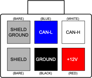
The connector used on the EV Driver Controls and other Prohelion devices is a 6-way 3mm pitch Molex MicroFit connector. The pinout is shown below, as viewed from the wire side – as you would look at it while inserting crimps. The colours shown match those in the standard DeviceNet CAN cabling pairs.
CAN Shielding
If the recommended braided shield is used in the cable, then terminate it to the SHIELD pin (lower-left corner on the connector) on both CAN IN and CAN OUT connectors on each device.
On one device only in the network, instead of using the SHIELD pin, terminate the shield to the SHIELD GROUND pin (upper-left corner on the connector) on both CAN IN and CAN OUT connectors, to ground the shield for the entire network at this single point. The usual place to do this is where power is fed into the network, typically at Prohelion 's EV Driver Controls product.
CAN Termination
To implement the required 120 Ohm termination resistor at each end of the CAN bus, plug a connector into the unused CAN connector on the last device at each end of the network with a resistor crimped into the appropriate locations.
Communications
The CAN standard does not specify high-level message protocols. Prohelion devices use a custom protocol, outlined in the communication specification document for each device.
By default, each device operates at 500 kbits/second, one step below the maximum possible data rate of 1 Mbit/second, and comes programmed from the factory with a CAN base address that will allow it to work without problems with other Prohelion devices. Currently, modifying the driver controls data rate or CAN base address requires reprogramming the microcontroller, although hardware support is provided to allow updates over the CAN bus in the future.
The WaveSculptor motor controller expects regular messages from the driver controls device. If a message is not received within a set timeout period then the controller will change to a safe mode and will stop driving the motor. This protects against faults where either a connector is loose or broken, the cable has been damaged, or the driver controls have failed.
Power Supply
The EV Driver Controls provides a means to connect power from the 12V car battery into the CAN bus, to power other devices on the network. The default software switches power to the CAN bus based on the state of the ignition key – the CAN bus will be powered if the key is in either the Accessories or the Run position.
System Expansion
Prohelion can provide a CAN bus LCD display capable of showing up to four different telemetry values (one at a time) on a 3.5 digit sunlight-readable screen. Multiple displays can be used if desired.
Multiple Motors
Multiple motors/controllers are accommodated easily with the CAN bus system. All that is required is for each WaveSculptor controller to be programmed to receive messages from the same driver controls base address, and then to run the vehicle in current-control mode (the default setup). Each motor will now operate at the same current, thus giving automatic wheel speed differences for cornering, with the system acting as an electronic differential.