Construction Procedure
-
Cut three 5m lengths of litz wire to wind in parallel. If a different type of litz wire from that specified is being used, then more or less bundles in parallel may be required. Some experimentation may be necessary to work out how much wire can be physically wound through the toroid. 36 turns in total are necessary to achieve the specified inductance. (see below)
-
Hold the three bundles together in a flat group, three bundles wide. Leave a 20cm tail of wire to start, and wind 19 turns onto the toroid. This should fill up one layer of wire, with no overlaps. There is no need to twist the bundles together but pay attention to keeping the tension of the wires reasonably constant, so that each bundle remains the same length as the others. (see below)
-
Wrap the winding so far with Kapton or Polyester tape, to hold the wire in place. Pay attention around where the tail exits the bundle, as this is the most likely place for vibration and abrasion to occur, and also where the highest voltage difference will be across the inductor. Before placing all the tape, consider using a marker pen to draw an arrow on top of the tape to indicate which direction the windings were wound. (see below)
-
Wind another 17 turns in a second layer, continuing to wind in the same direction as the first layer. It is important to have 36 turns in total when finished, and all turns in the same direction. Leave another 20cm tail where the winding exits the inductor.
-
Wrap the complete winding in another layer of tape. As before, pay attention to the exit tail area.
-
Dip the inductor in a container of transformer varnish or low viscosity potting compound. Much improved results will be achieved if this process is done in a vacuum chamber, as the varnish will then penetrate into the inner layer and will completely lock all the windings and the core together.
-
Cut the tails to the required length if necessary and use the solder pot to strip the insulation from the ends of each tail. Using pliers or some method to hold the wire (it will get hot!) dip each tail into the solder pot to a depth of 15 to 20mm. Hold it in the pot until the insulation stops bubbling up – this usually takes around 30 seconds. Warning: the fumes produced by this process can be toxic, take appropriate cautions with personal protective equipment or use a fume hood in a laboratory.
-
Insert the soldered wire end into the PP75 crimp or bolt lug, and crimp it with the appropriate tool. This will usually be a hex crimp tool capable of generating quite high forces.
-
If left at this stage, a good electrical contact will be in place, but over time the solder will 'flow' under the mechanical pressure of the crimp, and a loose and high-resistance joint will result. This can be fixed by using a gas torch (or possibly a hot-air gun or paint stripper) to heat the crimp past the solder reflow point so that the solder around the wire flows onto the inside of the crimp and forms a soldered connection. More solder can be added to the joint if necessary during this process.
Photos
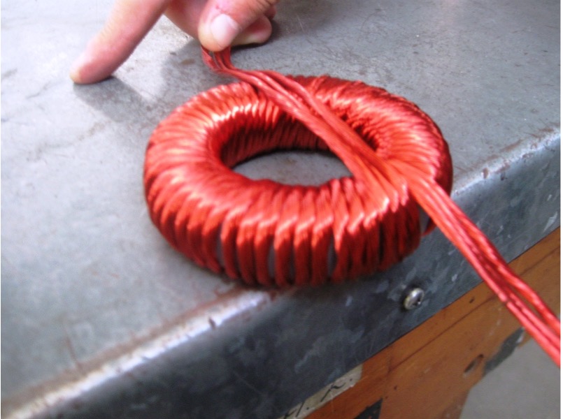
Inductor after completely winding the first layer, ready for taping:
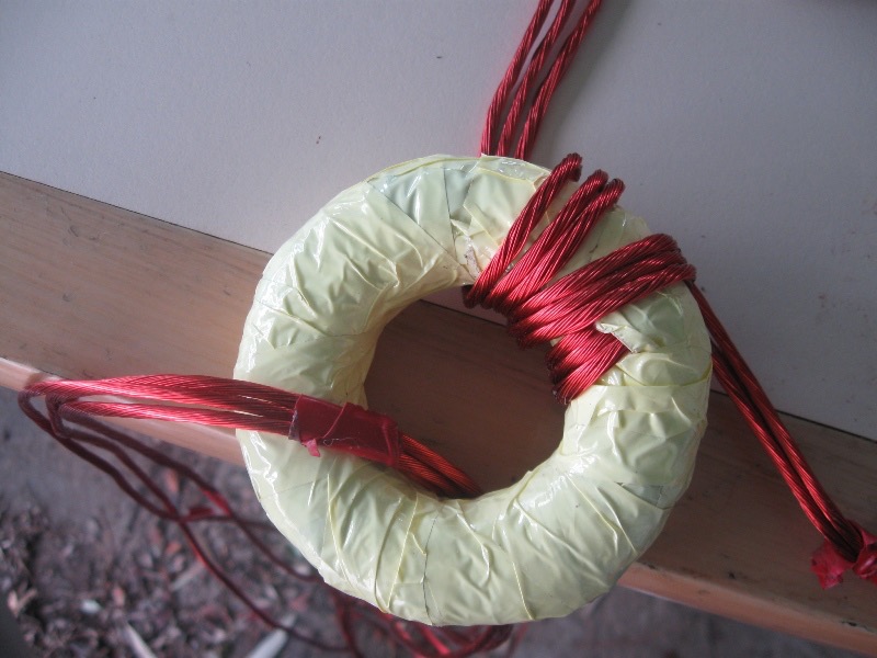
Inductor after taping first layer and beginning second layer:
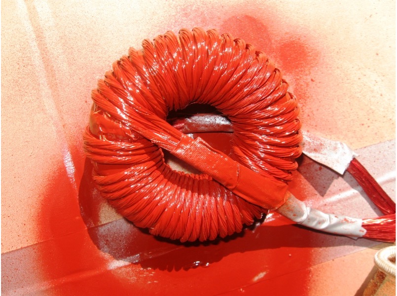
Inductor after spraying with transformer varnish. It is recommended to use a dip procedure for this step instead of spraying:
Photos courtesy of Erdem Guven, SAU Solarcar