WaveSculptor Motor Interface Type 7: Resolver and Thermistor
This document describes the function, interface, and properties of the WaveSculptor motor interface circuit, type 7.
Position Sensor
Type
The type 7 interface reads position information from a sin/cos resolver position sensor with analog outputs.
Drive
The interface board drives the resolver with a sinusoidal excitation signal of approximately 7V pk-pk at a frequency of 10kHz. This amplitude and frequency is factory settable to other options so can support other types of resolver if necessary.
These drive signals are commonly shown in resolver datasheets as:
- R1(Exc+)
- R2(Exc–)
Sense
Two channels of differential analog input are used, for the sin and cos sense windings.
These signals are commonly shown in resolver datasheets as:
- S1 (Sin+)
- S3 (Sin–)
- S4(Cos+)
- S2(Cos–)
SHIELD
Resolver signals can be quite sensitive to noise and therefore attention should be paid to shielding.
The motor interface board provides two possible shield signals:
- ground, and
- a shield generated from the average voltage of the Sin and Cos waveforms. If using a single-shielded cable, terminate the shield to the SHIELD pin, although terminating to GND will usually work equally well.
If using a dual shielded cable, terminate the inner shield to SHIELD, and the outer shield to GND.
Resolver Mount
To help prevent noise pickup from capacitive coupling, the resolver should be mounted such that its body is isolated from the motor frame. Do NOT tie the SHIELD or GND pins to the motor frame.
Connector
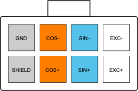
The connector used for the motor sense signals is a 8-way 3mm pitch Molex MicroFit connector. The pinout is shown below, as viewed from the wire side – as you would look at it while inserting crimps
Temperature Sensor
Type
The type 7 interface reads two channels of temperature information from NTC thermistors. Linearisation is provided in hardware on the motor interface circuit, with further scaling, offset and B curve correction being provided by the WaveSculptor, with inputs from the calibration software and the user.
Input
By default, the linearisation is provided for a 100k @ 25°C sensor, but this can also be chosen as a factory option for different values, such as the relatively common 10k @ 25°C parts.
Connector
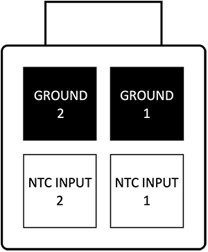
The connector used for motor temperature sense signals is a 4-way 3mm pitch Molex MicroFit connector. The pinout is shown below, as viewed from the wire side The pinout is shown below, as viewed from the wire side – as you would look at it while inserting crimps.
Motor Controller Interface
The interface to the WaveSculptor motor controller is provided using differential signal pairs transmitted by the motor interface, with three being received by timer channels in the WaveSculptor, and one being received by a serial UART peripheral. Regulated 5V and 12V power is provided by the WaveSculptor for use by the motor interface circuitry and sensors.
Connector
The connector used for motor sense signals is a 14-way 3mm pitch Molex MicroFit connector. The pinout is shown below, as viewed from the wire side – as you would look at it while inserting crimps.
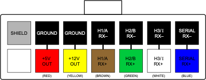
Wiring
The wiring for this connector must be implemented with twisted pairs, as the signal inputs are differential. Prohelion strongly recommends using Belden 9506 type cable (shielded 6 pair) for this connection, with suggested cable colours shown above.
Installation
Position
To minimise the length that low-powered signals from the position and temperature sensors have to travel, install the interface board as close to the motor as possible, usually inside the motor terminal box. Insulate it with heatshrink or similar if necessary.
Wiring
Wire a straight-through cable from the WaveSculptor to the motor interface board 14-pin connectors, using the twisted-pair cable recommended in the previous section.
Wire the position sensor to the 8-way connector.
Wire the temperature sensors to the 4-way connector.
Mechanical
The motor interface is supplied as an unenclosed PCB of dimensions 60x25mm. Approximate height including connectors is 12mm.