EV Driver Controls CAN Bus Communications Protocol Specification
This document describes the protocol used to communicate over a CAN bus connection to and from the Prohelion driver controls module.
CAN Configuration
Hardware
The CAN hardware interface used is compatible with the CAN 2.0B standard. The supported bit rates (bits per second) are 1 Mbps (default), 500 kbps, 250 kbps, 125 kbps, 100 kbps and 50 kbps.
Software
The CAN protocol uses data frames for most communication. Remote frames are also enabled. The identifier field uses the standard frame definition length of 11 bits. All measurement data is transmitted using IEEE single-precision 32-bit format (IEEE 754) with most significant byte (MSB) sent first.

Identifier
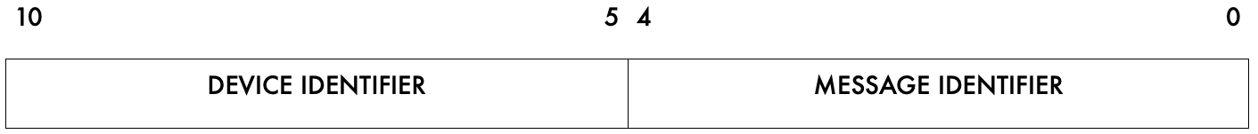
The identifier field has been split into two sections for Prohelion devices. Bits 10-5 contain the device identifier and bits 4-0 contains the message identifier associated with that device, as shown in Figure 2. This means that there is a maximum of 63 Prohelion device that can be on the CAN bus at any one time. The 64th location is reserved for the bootloader. Each Prohelion device can have 31 different types of messages. The first message identifier is used by the device identification message. Two device slots could be used if more messages per device were required, however this has not been required yet.
Data Field
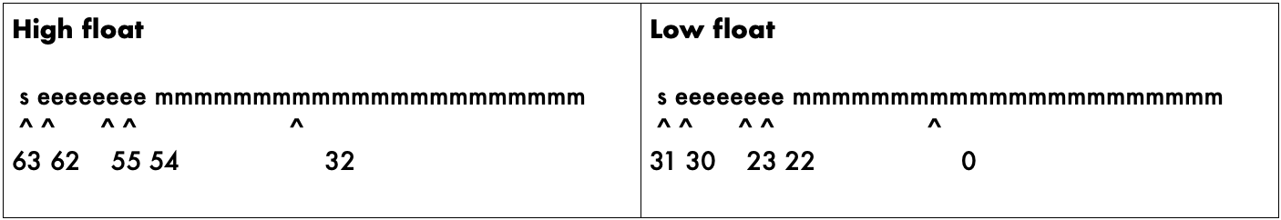
The data field in all frames is fixed at 8 bytes (64 bits) and two IEEE 754 32-bit floating point variables as shown in Figure 3. The data field is sent and expected to be received least significant bite first. This allows a direct overlay of a float[2] array and char[8] array on a little endian processor, such as, an Intel x86 (or clone) or the TI MSP430 in the driver controls.
Units
Please note that variables described in the following packets with units of percent “%” should be sent with a minimum floating-point value of 0.0 and a maximum value of 1.0. Do not send 100.0 as the maximum value.
Broadcast Frames
These are data frames broadcast from the driver controls to any listening motor controller. These commands contain desired set points for the control software to operate the controller. The commands are sent as required, however there is a maximum permissible delay between consecutive Motor Drive commands to prevent a timeout from occurring in the motor controller.
The driver controls also provide a convenient interface for a variety of switches and push buttons, that are not used directly by the motor controller. For example, another relay output module on the CAN bus may listen for the Switch Position frame and turn the indicator (blinker) lights on and off as appropriate.
Remote Frames
All frame types sent by the driver controls may also be requested on demand by using the CAN bus remote frame transmit (RTR) mechanism. This is accomplished by the remote device transmitting a frame containing the address (ID) of the frame request, with the RTR bit set. The driver controls will reply with the requested packet after a short delay. This mechanism is independent of the timer-based output of control frames from the driver controls.