Observation
This main screen shown in Figure 1, displays the status of WaveSculptor along with all available measurements. Communications between the configuration software and WaveSculptor is achieved via the Prohelion CAN-Ethernet bridge
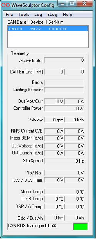
A Prohelion CAN-Ethernet bridge must be present on the same CAN bus as the WaveSculptor and on the same LAN as the PC running the configuration software. Before using the configuration software, you must first configure the CAN-Ethernet bridge as described in the CAN-Ethernet Bridge User's Manual.
Once the CAN-Ethernet Bridge is configured and the WaveSculptor CAN bus is powered up, all WaveSculptors present on the CAN bus will be listed. The list shows each devices CAN base ID, the type of WaveSculptor and the serial number. If there is more than one WaveSculptor present, select the one you wish to utilise.
No configuration information stored in the WaveSculptor is downloaded to the PC when it becomes selected in the list box allowing for simple and immediate telemetry monitoring functionality. The required configuration segments are downloaded on demand the first time when one of the tools in the menu are selected. The configuration download and upload progress is displayed in a separate pop-up window which also allows for the current transfer to be cancelled.
A CAN BUS traffic monitor is situated at the bottom of the screen which indicates the total traffic loading on the selected bridged network
Errors
Controller errors are presented in the text box labelled Errors. Different types of errors can occur. These errors usually would only occur one at a time, however it is possible to have multiple errors displayed at once.
NOTE: Devices that identify as V3 for their hardware version have an extended set of error flags. The possible error messages are listed below:
-
HWOC: Hardware Over current; A hardware comparator is used to generate this signal and if the current exceeds the hardware over current trip point for even an instant this error will occur. The hardware comparators monitor currents in both phase C and phase B.
-
SWOC: Software Overcurrent; This error occurs if the firmware on the controller samples a DC bus, phase C or phase B current that is above the limit set in the calibration section of the configuration file.
-
HWOV: Hardware Over Voltage; A hardware comparator is used to generate this signal and if the bus voltage exceeds the hardware trip point for even an instant this error will occur.
-
SWOV: Software Over Voltage; This occurs if the bus voltage exceeds the over voltage limit set in the calibration section of the configuration file. This is to protect the semiconductors against over voltage during regeneration.
-
HALL: Hall Sequence Error; This occurs if a hall transition is invalid. The hall sequence is recorded during the PhasorSense routine and this same sequence must be followed by the motor hall effect sensors at all times.
-
WD: Watch Dog; This is a warning message more than an error, as the controller will still function with this error. An independent hardware watchdog needs to be updated at least 4 times per second by the firmware in the controller. If it is not updated the controller will reset (something that the driver of the vehicle would feel as a short loss of power). This error will stay set until the controller is next reset or power cycled.
-
CFG: Configuration File Error; An error occurred while reading the configuration file, and will be flagged during the boot-up sequence of the WaveSculptor. If all or some of the configuration values cannot be read from the configuration file, default values will be used instead of the stored values. This error does not disable the controller, it will continue to operate in the best manner possible using the default configuration values. This does mean that the controller may not operate as expected. Unless the error is with one of the more critical configuration constants it may be difficult to even notice the difference in operation.
-
UV15V: Under Voltage15V; The internal 15V rail has dropped below 12V.
-
DESAT: Desaturation; On a WaveSculptor200 this could indicate an overcurrent desaturation of the IGBT switches or an under voltage of the IGBT driver IC. On a WaveSculptor22 this means an under voltage of the MOSFET driver IC.
-
MOT: Motor interface board missing; The WaveSculptor has not received any communication from the motor interface board within the last second.
-
OVSPD: The motor speed has exceeded the configured maximum by 15%. This error will automatically clear once the motor speed reduces to 95% of maximum.
-
OCpX: (V3 Only) Hardware Over current; This is the same as HWOC, except that it specifically identifies the phase that detected the fault. ‘X’ can either be B or C, for Phase B or Phase C respectively.
-
GhX / GlX: (V3 Only) Desaturation; This is the same as DESAT, except that it specifically identifies the phase that detected the fault and whether it was the high (‘h’) or low (‘l’) side gate. ‘X’ can either be A, B or C, for Phase A, Phase B or Phase C respectively.
Limiting Setpoint
The WaveSculptor runs six concurrent control loops, with the primary control loop regulating the motor current. There are also control loops regulating the velocity, bus current, maximum and minimum bus voltage and heatsink temperature. At any one time only one of these control loops is limiting the motor vehicles torque. The possible limiting setpoints are listed below:
-
PWM: Not enough bus voltage to be able to produce more current and hence more torque.
-
Iq: The motor current setpoint is being regulated in the motor. (Normal operation).
-
vel: The vehicle velocity setpoint has been reached. (Normal operation)
-
Idc: The bus current setpoint is limiting further increase in motor torque.
-
VdcMax: Motor regeneration torque is limited by the maximum bus voltage setpoint.
-
VdcMin: Motor drive torque is limited by the minimum bus voltage setpoint.
-
temp: The maximum heatsink setpoint has been reached and is limiting the motor torque.
Measurements
All measurements are broadcast from the WaveSculptor at periodic intervals, unless disabled in the configuration file. For more details, please refer to the CAN bus comms Appendix in the WaveSculptor User's Manual.
| Measurement | Description | Rate (Hz) |
|---|---|---|
Bus Voltage |
The input bus voltage of the controller | 5 |
Bus Current |
The input current to the controller | 5 |
Controller Power |
Bus Voltage * Bus Current, calculated on the PC | 5 |
Motor RPM |
Angular velocity of the motor in RPM | 5 |
Vehicle Velocity |
Vehicle Velocity in km/h | 5 |
Phase C Current<br>Phase B Current |
Phase B and C motor current in Arms. Relies on a RMS filter to smooth the motor frequency, so value may not represent true cycle RMS at very slow motor frequencies. | 5 |
BEMF (D) |
Component of the BEMF aligned with the motor flux. By definition this value is always zero. | N/A |
BEMF (Q) |
The motor back EMF. Represents the peak voltage | 5 |
Vout (D) |
Component of the controller output voltage aligned with the motor flux. | 5 |
Vout (Q) |
Component of the controller output voltage aligned with the motor BEMF and resistive voltage drop | 5 |
lout (D) |
Aligned with the motor flux, current in this component will weaken or strengthen the motor flux. | 5 |
lout (Q) |
This component of current produces motor torque and does actual work. | 5 |
Slip Speed |
The difference in speed between the rotor and the stator flux, only valid when driving induction motors | 5 |
15V Rail |
The voltage of the internal 15V rail, used to power the low voltage sections of the WaveSculptor. Note that this is NOT the value of the 12V CAN bus supply input. | 1 |
1.9V Rail |
The voltage of the 1.9V rail, used to power the core of the DSP. | 1 |
3.3V Rail |
The voltage of the 3.3 rail, used to power all the control circuitry | 1 |
Motor Temp |
The temperature of the connected motor in degrees Celsius | 1 |
Phase C Temperature |
Heatsink temperature under the phase C semiconductors. | 1 |
Phase B Temperature |
Heatsink temperature under the phase B semiconductors. WS200 ONLY. | 1 |
DSP Temperature |
The temperature on the surface of the DSP control board within the controller. | 1 |
Phase A Temperature |
Heatsink temperature under the phase A semiconductors. WS200 ONLY. | 1 |
Odometer |
The distance travelled (in km) since reset. | 1 |
Bus integrator |
The charge drawn from the bus in Amp.Hours since reset. | 1 |
Table 1: WaveSculptor Measurements
Please note that a mouse click on any of the measurement text boxes of Figure 1 will request the measurement from the DSP (using a CAN remote request). Hence, the measurements can still be read even if its periodic send flags are disabled in the configuration file.
Traffic Monitor
The CAN BUS traffic monitor situated at the bottom of the main screen is a useful indicator of the total traffic loading that is occurring on the selected bridge network. The traffic should be kept as low as possible in order to ensure smooth operation and communication between devices, especially when transferring configuration files or flashing devices. The colour indicator to the side of the load percentage changes relative to the level of loading giving a good quick indication of the network health.
| Colour | Description |
|---|---|
Black |
Not connected to a network or traffic is very low with respect to the sample rate of the monitor |
Green |
Connected to a network and within recommended traffic loading of up to 30% bus utilisation |
Yellow |
Greater than 30% bus utilisation (Not recommended normal operating levels) |
Red |
Greater than 60% bus utilisation (Bus is heavily loaded and there is a risk of packets failing to be sent or received) |
Table 2: CAN BUS traffic monitor status colours