Prohelion Batteries
Prohelion design and sells Battery Management Systems (BMS) designed for both automotive and fixed location environments.
The Prohelion Battery Management technology is built around three main components. The Battery Management Unit (BMU) which consists of a master board and a number of Cell Management Units (CMU)'s. In addition to the BMU and CMUs a typical Prohelion battery may also contain a 12v Control System which monitors the onboard 12v capabilities. For more information on these products, please see the main Prohelion Website.
Profinity supports the management and monitoring of the BMUs, CMUs and 12v systems via your profile.
A typical battery will generally only have one BMU, but larger packs or split packs like the ones used in racing can involve two or more BMUs. If your pack is configured like that then you simply add multiple BMUs to your profile with different base CAN addresses.
BMU Management
The top section shows data from the BMU, while the lower section shows CMU data – one row per CMU.
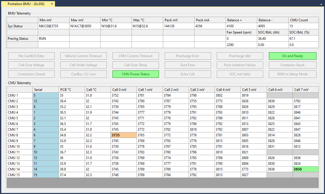
BMU DATA
The top row of BMU data presents the following information (left to right):
| Cell | Meaning |
|---|---|
Min mV |
Minimum voltage cell in the pack, and its voltage. The example shows Node (CMU) 8, Cell 0 is minimum, at 3699mV |
Max mV |
Maximum voltage cell in the pack, and its voltage. The example shows Node (CMU) 14, Cell 7 is maximum, at 3799mV |
Min C |
Minimum temperature cell in the pack, and it's temperature |
Max C |
Maximum temperature cell in the pack, and it's temperature |
Pack mV |
Total pack voltage |
Pack mA |
Total pack current |
Balance + |
Balance threshold voltage |
Balance - |
Balance threshold minimum voltage (balance voltage – hysteresis) |
CMU Count |
CMU count in system |
The next row shows Precharge status information on the left:
| Cell | Meaning |
|---|---|
Prechrg Status |
Current state (Idle, Precharge, Run, etc) |
| Contactor 12V supply voltage presence (mV on v4 or older BMUs) |
The buttons in the BMU section shows the various status flags, some flags are normal and show green when engaged, if buttons are showing orange or red then consult the BMU manual for more information.
Note that when not engaged or receiving messages from the control module the BMU will drop back to its safe precharge state which is the error state.
Consult the BMU documentation for more information but note that that error state can be part of normal operation.
-
CMU Power supply OK
-
Any cell OverVoltage
-
Any cell UnderVoltage
-
Any cell OverTemperature
-
Any cell untrusted
-
CMU and vehicle timeout errors
The right-hand side shows:
-
Fan speed for both fans
-
SoC and Balance SoC in Ah
-
SoC and Balance SoC in %
CMU DATA
The lower section of the program shows telemetry data from the CMUs, one row per CMU. The information shown is:
| Cell | Meaning |
|---|---|
Serial |
CMU Serial Number |
PCB C |
CMU circuit board (PCB) temperature |
Cell C |
CMU external (cell) temperature |
PCB C |
CMU circuit board (PCB) temperature |
Cell 0 ~ 8 mV |
1–8 cell voltage measurements |
The data is highlighted in various ways to quickly understand the system status
-
Cells currently balancing have a blue background
-
The minimum and maximum cells have bold text and are colour coded (green shows highest voltage, brown lowest)
-
Cell in yellow have trust errors
-
Cells not present (where the CMU has been programmed to monitor less than 8 cells) have no text, and a mid-gray background
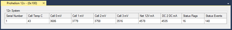
Prohelion 12 Volt Control System
Prohelion also offers a 12 volt control module that can be used to provide power to onboard 12 volt systems and is typically used in a racing environment. This module has a separate control panel that can be added to the profile and provides additional data on the performance of the 12 volt system.
Updating the BMU Configuration
To update the configuration of your Battery Management Unit, right mouse click on the BMU in the Profinity menu and select Configure Prohelion BMU. This will load the BMU configuration from the firmware and allow you to change it as desired.
Be Careful!
Changing the configuration of your BMU can lead to dangerous situations if you set the wrong values for your pack. Be careful and only make these changes if you know what you are doing and understand the purpose of these values.
Flashing the BMU Firmware
To flash the BMU firmware, right mouse click on the Update Firmware menu item on the BMU. A CAN to Ethernet bridge or a Virtual CAN Adapter is required for this operation.