Battery Management Unit
This section provides information on the Prohelion D1000 Gen2 Battery Management Unit (BMU).
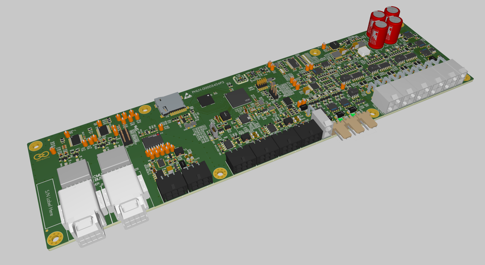
Figure 1: Prohelion BMS D1000 Gen2 BMU
Features
- 5 contactor outputs
- 3 low-side switches
- 2 non-isolated CAN bus networks (Internal and Charger)
- 1 isolated CAN bus network (External)
- Pressure and humidity sensor
- VOC and NOx sensor
- Temperature sensors
Specifications
| Parameter |
Value |
| BMS Supply Voltage |
12 V / 24 V (two variants) |
| BMS Supply Current |
80 mA (excluding contactors) |
Dimensions
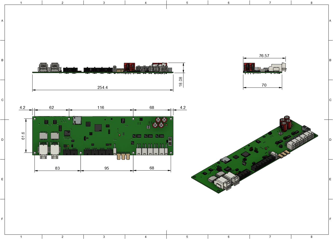
Figure 2: Prohelion BMS D1000 Gen2 BMU Drawing 1
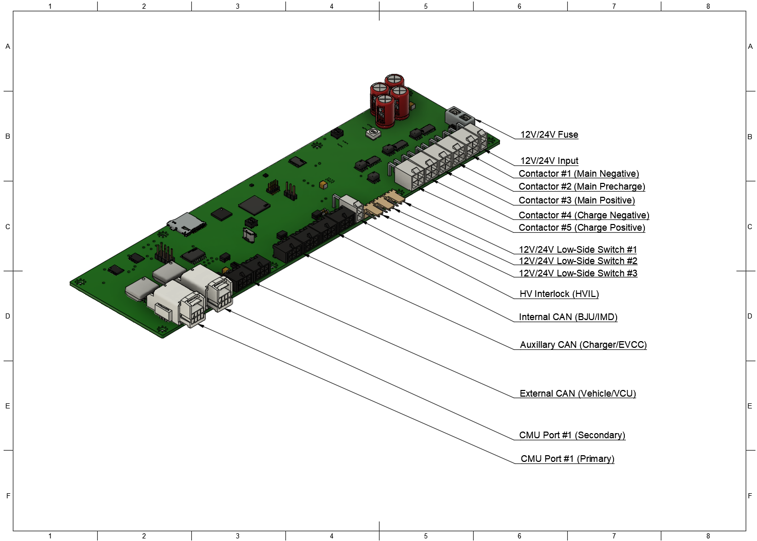
Figure 3: Prohelion BMS D1000 Gen2 BMU Drawing 2
Connectors and Pinouts
| Connector Name |
Receptacle Part Number |
Plug Part Number |
| 12V/24V Input Port |
Wurth WR-MPC4 649002227222 |
Wurth WR-MPC4 649002113322 |
| Contactor Ports |
Wurth WR-MPC4 649004227222 |
Wurth WR-MPC4 649004113322 |
| Low-Side Switch Ports |
Wurth WR-WTB 61900319521 |
Wurth WR-WTB 61900311621 |
| HVIL Port |
Wurth WR-MPC4 649002227222 |
Wurth WR-MPC4 649002113322 |
| CAN Ports |
Wurth WR-MPC3 66200621022 |
Wurth WR-MPC3 662006113322 |
| CMU Communication Ports |
JAE Electronics MX34R08HF4T |
JAE Electronics MX34008SF4 |
| Pin Number |
Label |
| 1 |
BMS Input Power+ (12V/24V) |
| 2 |
BMS Ground |
| Pin Number |
Label |
| 1 |
Contactor Power+ (12V/24V) (switched) |
| 2 |
Auxiliary Power+ (12V/24V) |
| 3 |
Contactor Ground |
| 3 |
Auxiliary Ground (sense) |
Low-Side Switch Port Pinout
| Pin Number |
Label |
| 1 |
Ground (switched) |
| 2 |
Power+ (12V/24V) |
| 3 |
Auxiliary Ground (sense) |
HVIL Port Pinout
| Pin Number |
Label |
| 1 |
HVIL Out |
| 2 |
HVIL In |
CAN Communication Port Pinout
| Pin Number |
Label |
| 1 |
CAN Power+ (12V/24) |
| 2 |
CAN Ground |
| 3 |
CAN Shield |
| 4 |
CAN High |
| 5 |
CAN Low |
| 6 |
CAN Ground |
CMU Communication Port Pinout
| Pin Number |
Label |
Pin Number |
Label |
| 1 |
TX Positive |
5 |
TX Negative |
| 2 |
Not Connected |
6 |
Not Connected |
| 3 |
Not Connected |
7 |
Not Connected |
| 4 |
RX Negative |
8 |
RX Negative |